In week 3, we attended our very first practical lesson for this module
-> "Reverse Engineering"👷🔧☕
💥Objectives of the Practical:
identify the parts BD100® coffee maker
explain the function of each part
explain the relationship among the parts
determine the heating energy.
💥What did we do in the practical?
📌1. Reverse Engineering-> Dismantling Coffee Maker BD100®☕
Image 1: Coffee Maker (BD100®) Before Dismantling [SIDE VIEW]
Image 2: Coffee Maker (BD100®) Before Dismantling [TOP VIEW]
Image 3: Process of removing Filter from Coffee Maker (BD100®) [Featuring Kenny]
Image 4a
Image 4a-c: Components of Filter that was removed in Image 3
Image 5: Top view of Coffee Maker (BD100®) without Filter
Process of Dismantling Bottom Part STARTS! ✅
Image 6: Unscrewing screws of Bottom part of Coffee Maker (BD100®) -> To take note of the components inside the Coffee Maker
Image 7: Screws stored after unscrewing in Image 6
Image 8: Exposed internal parts of the Coffee Maker after unscrewing in Image 6
Image 9: Process of Unscrewing Screws from Image 7 ]Featuring Serena, Kenny and Kai Rong]
Image 10: Screws unscrewed
Image 11: Screws Stored after unscrewing in Image 9
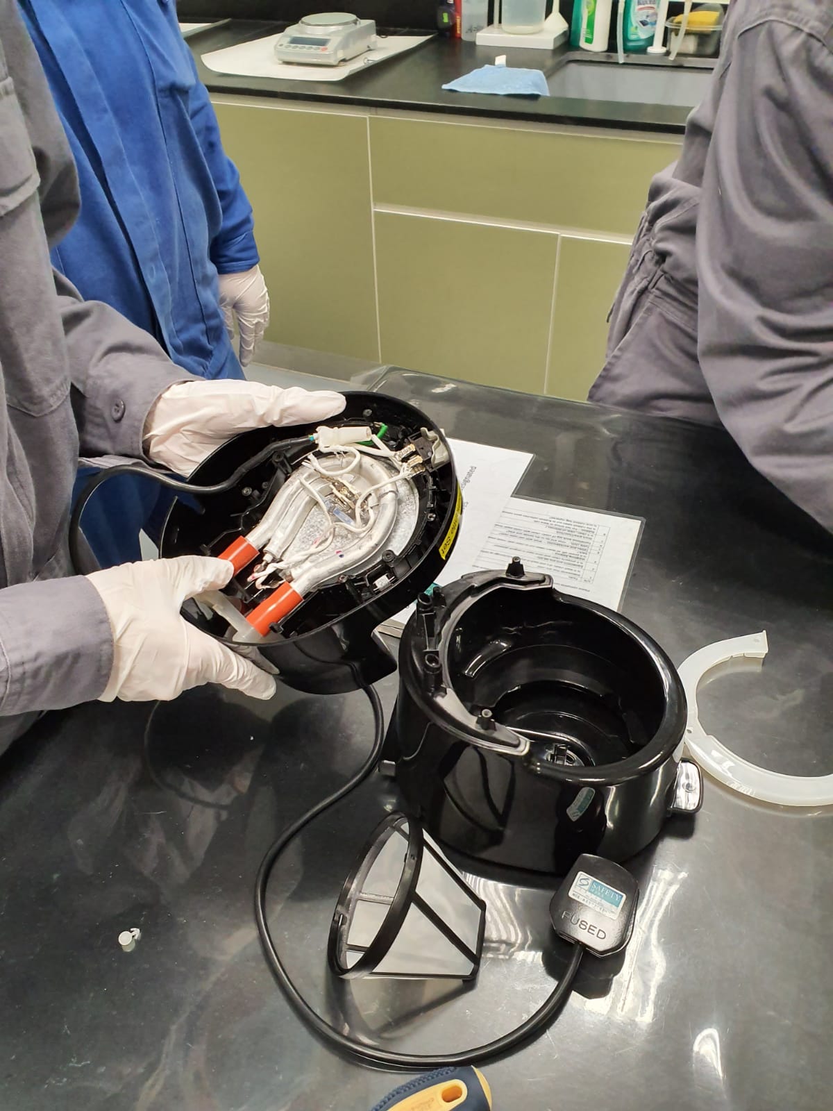
Image 12: Process of further dismantling, brainstorming and examining components whilst trying to identify them and their functions in heating the water as well as "line tracing" the water flow.
*We applied a skill that we had learned in our Lab and Process Safety II module last semester in Year 1: line tracing in this practical. Although line tracing is mainly used in a pilot plant, it was useful in this situation to trace the path the water travels. We line traced the electrical line to see how the heating element works. (Conversion of Electrical energy to Heat energy supplied to the Heating element) which will heat up the water. After the line tracing, we discovered there is a part of the coffee maker with a valve and we had to figure out what the function of the valve was:
Image 13: Check Valve
The circled orange tube contained a check valve inside.
Recall Fluid Flow Module in Y1 : (HOW A CHECK VALVE WORKS?)✅
The function of a check valve is to prevent backflow of liquid thus we had to figure out which side to put the check valve on as we can orientate the tubes 2 ways however the wrong way would distrupt the flow of water. Thus, we figured it out by allowing water to flow into the valve to see whether water will flow out as we were line tracing the flow of water. (pictured below in Image 14)
Image 14: Water flow in tubing with check valve
VERSUS
Image 15: Flow of water in Tubing without Check valve
Determining the Water Flow✅
Image 16: Tracing the Water Flow
Image 17: Schematic Diagram of Coffee Machine (Side View) showing water flow
Operating Principle of Coffee Machine✅:
As illustrated by Image 17, the side that has the check valve is the inlet which is at the reservoir. Here water from the reservoir enters, get heated by the heating element (electrical energy from electrical wire converted to heat energy supplied to cool water). The operating principles is when water flows down from the water reservoir it passes through the water piping near the heating element which then heats up the water at the inner wall of the piping. Some of the water here gains enough heat to be vapourised giving rise to a water-vapour mixture. To prevent the backflow of the heated water with vapour mixture back to the reservoir, a check valve is installed along the piping near the water reservoir, facing downwards. The heated water with vapour mixture will then pass through the pipe and the vapour rises upwards to the filter paper due to its low density while pushing the hot water up against gravity. This creates an air bubble pump - the mechansim through which the vapour pushes the hot water upwards. As the vapour in the hot water-vapour mixture that pushes the hot water rises up, away from the heat source below, it condenses into water. The vapour now condensed to water and hot water pushed up, flows into the filter paper, contacting the coffee powder on the filter paper where leaching occurs. That is, the soluble solute in the coffee powder upon contact with the hot water will dissolve in the hot water and drip down through the filter paper into the jug, being collected as brewed coffee solution.
Eventually, when we were done observing and deducing what each component does, we reassembled the parts back together and screwed back the screws that was initially removed.
Image 18: Reassembled Coffee Machine
📌EXPERIMENT: Determining Heating Energy Required-> Coffee Maker in ACTION
We then had to brew coffee in order to determine the heating energy required by the Coffee Maker.
Image 19: Taping the cover of the coffee machine to prevent escape of water as water vapour
Data Collection before experiment✅:
We measured the mass of the filter paper and mass of coffee powder used using a weighing scale. Then measured the volume of the water used (the aftermath is shown in Image 20). Then we measured the surrounding temperature (room temperature) from the air-conditioner controller, starting water temperature (See image 21) and the average temperature of the coffee powder before it was put in the machine.
Image 20: 300ml of water in a beaker (after measured in a measuring cylinder)
Image 21: Measuring start temperature of the water using a thermometer and temperature probe (can just use one instrument to measure temperature actually 😅)
Image 22: Electricity Consumption Monitor -> Indicates power consumed
Image 23: Electricity Consumption Monitor Connected to Coffee Machine (Water has been poured into Jug and inserted in Coffee Machine already - not shown)
Image 24: Measuring starting temperature of coffee beans
Image 25: Top View of Coffee Machine with Coffee Powder added
Start of Experiment!✅
We proceeded to make our coffee. As the coffee was being made, we took notice of the time for the coffee to be brewed - Shown in the video below (Time is shown on Electricity Consumption Monitor as well). We set an interval of 30 seconds until the coffee has been fully brewed and no more flow of coffee is seen into the Jug.
Image 26: An instance during the experiment as coffee was brewing
- End of Experiment✅
Image 27: Post experiment with condensate on lid and spent coffee powder shown
Image 28: Measuring temperature of spent coffee grounds
Post Experiment Data Collection✅:
We measured the mass of the wet coffee filter, spent coffee powder, volume of the brewed coffee, mass of the brewed coffee and the final temperature of the brewed coffee. Since there was condensate on the lid, we also had to take note of it as we used material balance in order to find the mass of the condensate on the lid. We did this by estimating the amount of water that vapourised and condensed on the lid of the water tank by comparing the mass of a dry paper towel to that of its mass when it was used to wipe the condensate off the lid. From all these data, we calculated the energy that was transferred to the coffee and hence was able to determine the energy efficiency of BD100 by calculating the energy transferred to the coffee divided by the electricity it consumed that was read off the electricity consumption monitor. From the data shown in the video on the Electricity Consumption Monitor, we tabulated the power consumed every 30 seconds and converted it into energy consumed whereby we could find the average energy consumption.
📌Housekeeping
After recording all the data, we cohesively cleaned up our table. After allowing the coffee maker to cool we cleaned the exterior of the coffee maker with a moist cloth, removed the detachable components such as the filter holder, permanent filter, water tank, cover and jug to clean individually. The filter paper and spent coffee powder was disposed. We then washed the detachable components and reassembled them back into the coffee maker. When all groups were done, there was a small debrief and briefing for practical 2. Class dismissed.
💥Team Roles and Responsibilities:
Team Leader + Blogger: Serena -> She ensured coordination within the team and led the team through the different steps of the dismantling and experiment processes, as she had to be well read with the entire experiment. She is responsible for blogging the entire practical.
Researcher + Technical Executive: Kai Rong -> He was in charge of finding out how the coffee maker works, researched on the spot about certain concepts we werent familiar with e.g. air-lift pump when we were line tracing the water flow and were brainstorming the coffee maker's operating principles. Together with Kenny, he also helped out with the technical aspects of the practical e.g dismantling, carrying out the experiment physically.
Main Technical Executive: Kenny -> He was in charge of the technical aspects of the practical e.g dismantling, carrying out the experiment physically, together with Kai rong.
Photographer +Time Keeper: Jerome -> He captured the team in action with his clicks and captured various photographs/videos essential for documentation of the practical in the blog. He was in charge of keeping the team in check by reminding us of the time we spent and had left.
💥Challenges Faced😖 + How we overcame them💪:
1. When we were dismantling the machine and removing the screws, some of the screws were hidden deep down inside the machine and it was difficult to get them out even after unscrewing them. Thus, our lab technician suggested using pliers to grab them out instead so that the screws will be taken out and kept well so that it can be installed back in after. She also advised us to use masking tape to label all screws taken out from the machine so that we will know where should the various screws be screwed back when reassembling. However despite using pliers we still couldnt retrieve the screws it was after shaking the entire machine that we could retrieve them out. We then payed heed to the lab tech's suggestion.
2. When we were reassembling the machine back together, certain components could not fit in its original position. Thus, we had to ask for help from the lab technical executive to help us with certain re-assembly parts. After much struggle, we managed to piece the machine back together.
3. To effectively take down the power consumption of the machine we decided to record a video and record down at the same time to reduce inaccuracies.
💥Reflections:
Together, we worked well together with good coordination of our actions and thoughts to ensure that the practical was done efficiently and with high quality. We provided constant reminders to inform our teammates about the teacher's progress as compared to ours. We payed close attention to Dr. Noel and the lab technical executive, following their instructions carefully to ensure that we had no room for errors. Overall, it was a fun first practical in year 2 so far! 😊🌈


Comments
Post a Comment